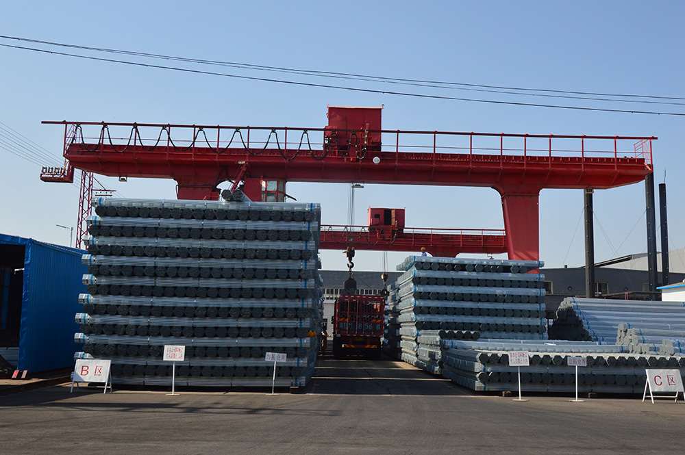
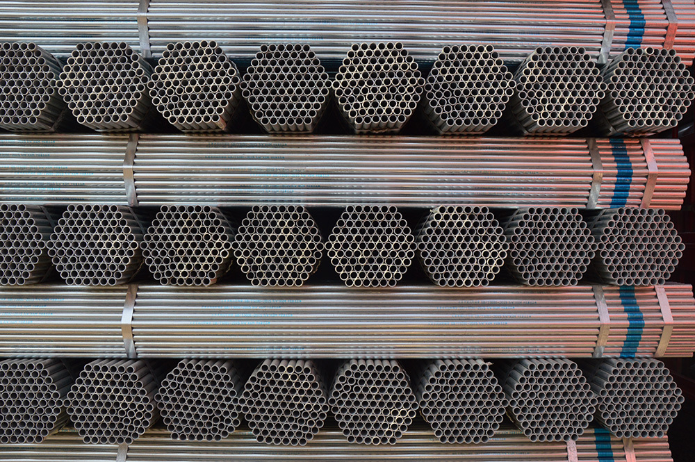
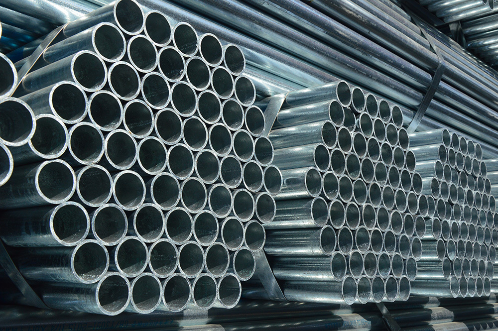
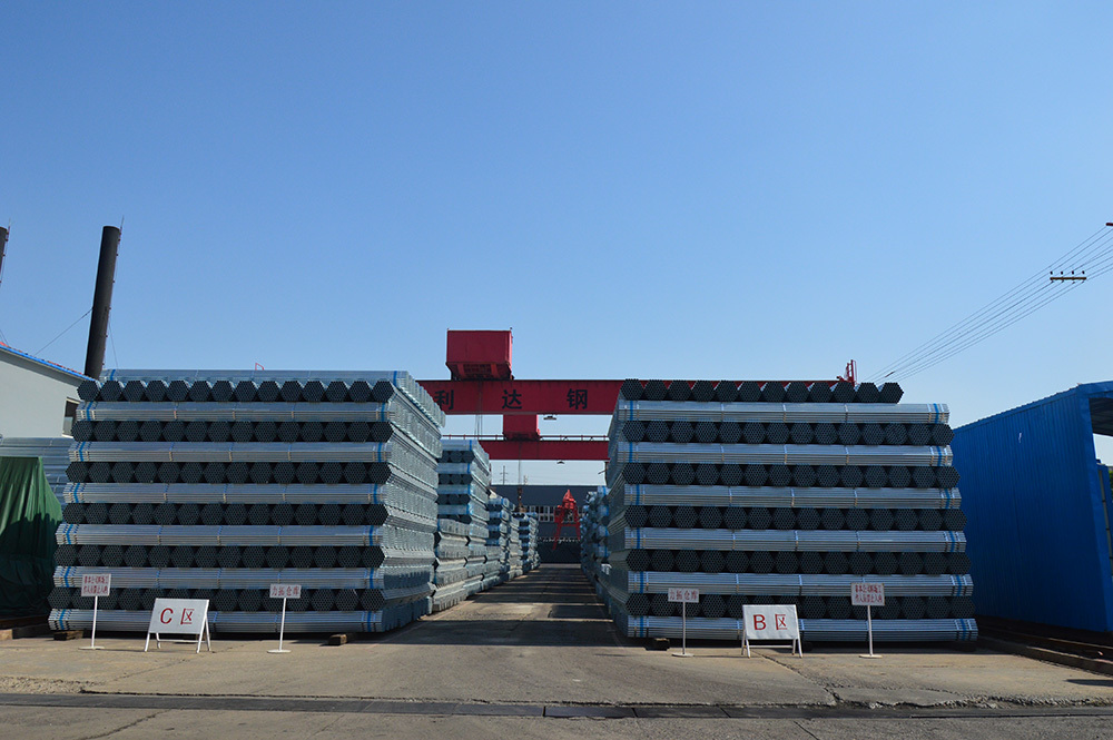
Lida brand steel-plastic composite pipe
Key words:
Lida brand steel-plastic composite pipe
Classification:
Product Introduction
Hot-dip galvanized pipe is produced by reacting molten metal with an iron substrate to create an alloy layer, thereby combining the substrate and coating. Hot-dip galvanizing first involves pickling the steel pipe to remove iron oxide from the surface. After pickling, the pipe is cleaned in a solution of ammonium chloride or zinc chloride, or a mixture of both, before being sent to the hot-dip galvanizing tank. Hot-dip galvanizing has advantages such as uniform coating, strong adhesion, and long service life. The steel pipe substrate undergoes complex physical and chemical reactions with the molten plating solution, forming a corrosion-resistant, tightly bonded zinc-iron alloy layer. The alloy layer, pure zinc layer, and steel pipe substrate are integrated. Therefore, it has strong corrosion resistance.
1. Grade and Chemical Composition
The grade and chemical composition of the steel used for galvanized steel pipes should conform to the grade and chemical composition of steel for black pipes as stipulated in GB 3092.
2. Manufacturing Method
The manufacturing method (furnace welding or electric welding) of black pipes is selected by the manufacturer. Galvanizing uses the hot-dip galvanizing method.
3. Threads and Pipe Fittings
3.1 For galvanized steel pipes delivered with threads, the threads should be machined after galvanizing. The threads should conform to the provisions of YB 822.
3.2 Steel pipe fittings should conform to the provisions of YB 238; malleable cast iron pipe fittings should conform to the provisions of YB 230.
4. Mechanical Properties The mechanical properties of the steel pipe before galvanizing should conform to the provisions of GB 3092.
5. Uniformity of Galvanized Coating Galvanized steel pipes should be tested for the uniformity of the galvanized coating. The steel pipe sample should not turn red (copper color) after being continuously immersed in copper sulfate solution 5 times.
6. Cold Bending Test Galvanized steel pipes with a nominal diameter of no more than 50mm should undergo a cold bending test. The bending angle is 90°, and the bending radius is 8 times the outer diameter. During the test, no filler is used, and the weld of the sample should be placed on the outer or upper side of the bending direction. After the test, there should be no cracks or peeling of the zinc layer on the sample.
7. Hydraulic Test The hydraulic test should be carried out on the black pipe, and eddy current flaw detection can also be used to replace the hydraulic test. The test pressure or eddy current flaw detection should conform to the provisions of GB 3092.
The mechanical properties of steel are important indicators to ensure the final use performance (mechanical properties) of steel, which depends on the chemical composition and heat treatment of the steel. In steel pipe standards, according to different use requirements, tensile properties (tensile strength, yield strength or yield point, elongation) as well as hardness and toughness indicators, and high and low temperature performance required by users are specified.
① Tensile Strength (σb)
In the process of tensile testing, the maximum force (Fb) sustained by the sample at the time of fracture, divided by the original cross-sectional area (So) of the sample, is called tensile strength (σb), with the unit of N/mm2 (MPa). It represents the maximum ability of a metal material to resist fracture under tensile stress. The calculation formula is:
Where: Fb - Maximum force sustained by the sample at fracture, N (Newton); So - Original cross-sectional area of the sample, mm2.
② Yield Point (σs)
For metal materials with yield phenomenon, the stress when the sample continues to elongate without increasing the force (remains constant) during the tensile process is called the yield point. If the force decreases, the upper and lower yield points should be distinguished. The unit of yield point is N/mm2 (MPa).
Upper yield point (σsu): The maximum stress before the force first decreases when the sample yields;
Lower yield point (σsl): The minimum stress in the yield stage when the initial instantaneous effect is not considered.
The calculation formula for the yield point is:
Where: Fs - Yield force (constant) during tensile testing of the sample, N (Newton); So - Original cross-sectional area of the sample, mm2.
③ Elongation after Fracture (σ)
In the tensile test, the percentage of the increase in length of the gauge length after the sample is broken to the original gauge length is called elongation. It is represented by σ, with the unit of % . The calculation formula is:
Where: L1 - Gauge length of the sample after fracture, mm; L0 - Original gauge length of the sample, mm.
④ Reduction of Area (ψ)
In the tensile test, the percentage of the maximum reduction in the cross-sectional area at the necking point after the sample is broken to the original cross-sectional area is called the reduction of area. It is represented by ψ, with the unit of %. The calculation formula is as follows:
Where: S0 - Original cross-sectional area of the sample, mm2; S1 - Minimum cross-sectional area at the necking point after the sample is broken, mm2.
⑤ Hardness Indicators
The ability of a metal material to resist the indentation of a hard object on its surface is called hardness. According to different test methods and applicable ranges, hardness can be divided into Brinell hardness, Rockwell hardness, Vickers hardness, Shore hardness, microhardness, and high-temperature hardness. For pipe materials, Brinell, Rockwell, and Vickers hardness are generally used.
A. Brinell Hardness (HB)
A steel ball or hard alloy ball of a certain diameter is used to press into the surface of the sample with a specified test force (F). After a specified holding time, the test force is removed, and the indentation diameter (L) on the surface of the sample is measured. The Brinell hardness value is the quotient obtained by dividing the test force by the spherical surface area of the indentation. It is represented by HBS (steel ball), with the unit of N/mm2 (MPa).
Notes:
1. Galvanized steel pipes can be used for conveying water, domestic sewage, fuel gas, air, heating steam and other low-pressure fluids, or for structural purposes.
2. Galvanized steel pipes can be connected using welding, threading, flanges, and grooved joints; if users need to use press-fit connectors, this must be specified before purchasing, and our company will treat it as a special-purpose steel pipe; the steel pipe should not be sharply bent; steel pipes with a nominal diameter of no more than 50mm are allowed to be bent, and the bending radius must be greater than 8 times the steel pipe diameter.
3. During installation and use, users should perform appropriate anti-corrosion treatment on the steel pipes according to the project needs. The outer surface of the galvanized steel pipe must not be in direct contact with building materials containing strong alkalis (such as lime), acids, and salts (sea sand) (the steel pipes must be protected to isolate them from such materials) to prevent corrosion; at the same time, appropriate materials, outer diameters, and wall thicknesses should be selected according to the project requirements to ensure the strength of the pipelines or structural components; corrosion losses caused by the lack of anti-corrosion or isolation treatment in environments with strong corrosive gases are not the responsibility of our company.
4. Must not be used for high-temperature, high-pressure pipelines such as boilers. Special-purpose steel pipes must be specified before purchase.
5. During the installation and lifting of steel pipes, handle with care, and be careful not to violently bump or scratch them, so as to avoid damaging the galvanized layer and affecting the corrosion resistance of the steel pipes. Store them indoors as much as possible.
6. Steel pipes should be cut using mechanical methods, and the cross-section should be perpendicular to the central axis. Allowable deviations are: for pipes with a diameter of no more than 100mm, the deviation should not exceed 1mm; for pipes with a diameter greater than 125mm, the deviation should not exceed 1.5mm
Previous:
The next one:
Related Products
Messages
If you are interested in our products, please leave your email, we will contact you as soon as possible, thank you!


